Product Details:
Payment & Shipping Terms:
|
Standard: | IEC62196-1, IEC60884, IEC60669-1, IEC62052-31 | WorkingPower: | AC 220V/50Hz |
---|---|---|---|
Working Station: | 1 Or Can Be Customized | Working Speed: | 10±2Rpm |
Test Height: | 250-500 Adjustable | Bushing Rotation Diameter: | 75mm And 76mm |
Applied EUT: | Connectors And Terminals | Warranty: | 12 Months |
Highlight: | IEC 62196-1 Test Apparatus,10Rpm IEC 62196-1 Test Apparatus,VE Conductors IEC 62196-1 Test Apparatus |
1. Introduction of apparatus for checking damage to VE conductors:
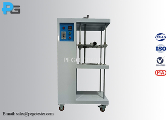
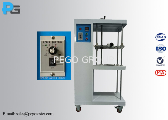
The apparatus for checking damage to EV conductors is designed to meet the test requirements of IEC62196-1 clause 13.3 figure 12, IEC60884-1:2022 clause 12.2.5 and figure 13, IEC60669-1 clause 12.2.5 and figure 9, IEC62052-31 clause 6.9.7.3 (for flexion test). The apparatus adopts guide rail screw structure, it consists of case, mass, bushing, etc. The number of tests can pe preset before use, when reached the set test times, the apparatus will automatically stop and alarm. The apparatus is used to checking if the terminal with screw clamping or screwless clamping can withstand the mechanical stress in normal use, and judging whether the design and structure of the screw clamping terminal meet the requirements of not excessively damaging the conductor when it clamps the conductor.
Testing method:
The end of the conductor is passed through an appropriate-sized bushing in a platen, positioned at a height H below the accessory, as given in Table 3. The bushing is positioned in a horizontal plane, such that its centre line describes a circle of 75mm diameter, concentric with the centre of the clamping unit in the horizontal plane. The platen is then rotated at a rate of (10±2)r/min.
The distance between the mouth of the clamping unit and the upper surface of the bushing shall be within 15mm of the height in table 3. The bushing may be lubricated to prevent binding, twisting or rotation of the insulated conductor. A mass, as specified in table 3, is suspended from the end of the conductor. The duration of the test is 15min.
During the test, te conductor shall neither slip out of the clamping unit nor break near the clamping unit.
Terminals shall not, during this test, damage the conductor in such a way as to render it unfit for further use.
2. Specification of apparatus for checking damage to EV conductors:
Model | PG-ADG | PG-ADG1 | PG-ADG2 |
Control mode | Electric control | ||
Working station | 1 | ||
Working speed | 10±2r/min | ||
Bushing rotation diameter | 75mm | ||
Test time | 0-99min59s (test time can be preset, and stop automatically when time up) | ||
Configured mass | 0.3KG, 0.4KG, 0.7KG, 0.9KG, 1.4KG, 2.0KG | 0.3KG,0.4KG, 0.7KG, 0.9KG, 1.4KG, 2.0KG | 0.4KG, 0.7KG, 0.9KG, 1.4KG, 2.0KG, 2.9KG, 4.5KG, 6.8KG, 9.5KG |
Test height | 260mm, 280mm | 260mm, 280mm, 300mm | 260mm, 280mm, 300mm, 320mm, 343mm |
Diameter of f bushing hole | 6.5mm, 9.5mm | 6.5mm, 9.5mm, 13mm | 6.5mm, 9.5mm, 9.4mm, 13.0mm, 14.5mm, 15.9mm |
Height adjusting mode | Manual adjustable | ||
Maximum conductor cross-section it can test | ≤10.0mm2 | ≤25.0mm2 | ≤50.0mm2 |
Dimension and weight | L530mm*D500mm*H800mm/80kg | ||
Working power | AC220±10%, 50/60Hz | ||
Working condition | 5-35℃ (temp.), 30%-90%R.H. | ||
Standard conform to | IEC60884-1 clause 12.2.5/figure 13
| IEC60669-1 clause 12.2.5/figure 9 | IEC62052-31 clause 6.9.7.3/figure H.1 |
Table 3 - Values for flexing under mechanical load test
Nominal cross-sectional area (mm2) | Diameter of bushing (mm) | Height a | Mass |
1.0 | 6.5 | 260 | 0.4 |
1.5 | 6.5 | 260 | 0.4 |
2.5 | 9.5 | 280 | 0.7 |
4.0 | 9.5 | 280 | 0.9 |
6.0 | 9.5 | 280 | 1.4 |
10.0 | 9.5 | 280 | 2.0 |
16.0 | 13.0 | 300 | 2.9 |
25.0 | 13.0 | 300 | 4.5 |
35.0 | 14.5 | 300 | 6.8 |
50.0 | 15.9 | 343 | 9.5 |
70.0 | 19.1 | 368 | 10.4 |
95.0 | 19.1 | 368 | 14.0 |
120.0 | 22.2 | 406 | 14.0 |
150.0 | 22.2 | 406 | 15.0 |
185.0 | 25.4 | 432 | 16.8 |
240.0 | 28.6 | 464 | 20.0 |
300.0 | 28.6 | 464 | 22.7 |
400.0 | 31.8 | 495 | 50.0 |
500.0 | 38.1 | 572 | 50.0 |
630.0 | 44.5 | 660 | 70.3 |
If a bushing with the given hole diameter is not adequate to accommodate the conductor without binding, a bushing having the next largest hole may be used. | |||
a Tolerance for height H:± 15mm |
3. Figures:
Contact Person: Ms. Penny Peng
Tel: +86-18979554054
Fax: 86--4008266163-29929